Creating modular industrial buildings for Condor
Posted: Wed Oct 16, 2019 11:24 am
Creating modular industrial buildings for Condor
Generality
We have already shown how to make buildings specifically dedicated to airports in the airport creation guide.
But in the Condor2 scenery, you can see that there are many industrial areas, usually empty of buildings, and that especially around airports.
In order to populate these industrial areas without weakening the FPS, it is necessary to create buildings with simple shapes and to have few textures to be loaded during the simulation.
To realize this type of building, we will use well-known properties of the UV Map because:
- The maps are repeated to infinity in the squares the UV Map.
- The textures are snapped on the vertices of the object unfolded on the map, and if we adopt a vertical or horizontal development there will be little or no deformation, if we take care to make simple roofs.
It is therefore a matter of creating linear textures that are automatically adapted to industrial buildings having a specific module, corresponding to the width or to the height of the texture.
Preliminary choices
The first choice to make is to determine the horizontal or vertical direction that will be used for the texture. For industrial buildings, since there is rarely vertical development, the horizontal direction is chosen. But if we want to create industrial buildings with important vertical development, like silos, we would probably, but not certainly, choose the vertical direction.
To be as versatile as possible, we have decomposed this modular industrial building into four distinct horizontal stripes.
- The roof with these translucent sky domes.
- The facades on the ground floor, including industrial doors, office doors, windows, which must remain at the right scale.
- Facade cladding connecting the ground floor and the roof of a variable height
- Basements, because the ground is not always flat, especially for large industrial buildings and it is illusory to flatten all industrial areas concerned or the floor of each building.
The roofs will be flat, or with one or double slope.
Then we have to make choices for both the building and the texture and after some tests, we have adopted the following provisions:
- A 5 meters module for building facades and roofs
- A basic texture in 1024 × 1024 pixels, which represents a base length of 30 m × 30 m.
A better choice would have been 900 x 900 pixels or 1200 x 1200 pixels because calculations are less complicated to manage.
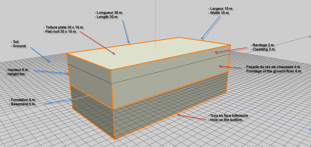
- A reference building with a flat roof of 30 x 15 m, height 6 m, basement 5 m, with a hole for the bottom.
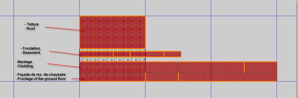
Each of the four horizontal stripes occupies a determined space in the texture map:
- The roof occupies half of the texture at the top, i.e. 512 pixels and 15 m wide.
- The ground floor facade, 138 pixels to 4 m high
- The cladding, not detached from the facade and above the facade, 172 pixels to 2 m high will be of variable height. The cladding texture will only be made with vertical patterns.
- The basements occupy part of the space between the roof and the facade. Here too, the height of 5 m can be variable to adapt to the terrain. The texture must be with a united or a vertical pattern.
Other choices are obviously possible.
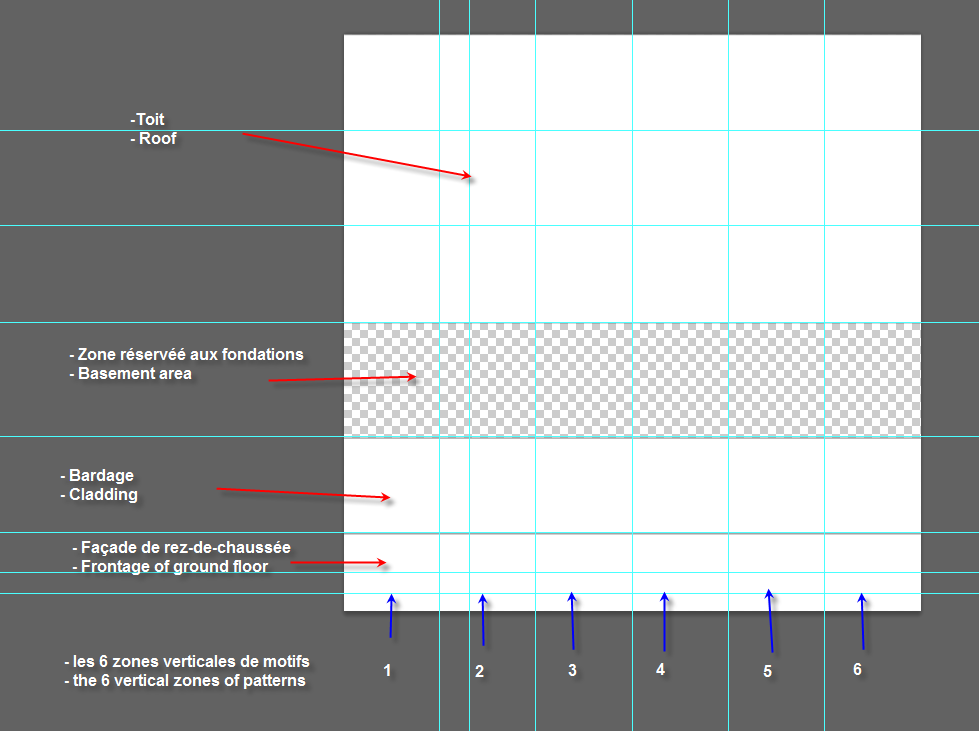
The 5 m module for facades and roofs allows to create 6 vertical zones, thus 6 possibilities to create an original pattern for these 2 entities. This succession of 6 patterns will therefore be repeated along each side of the building and on the roof, provided that the length and width of the building is a multiple of 5 m.
For the roof the succession of 6 patterns (2 are usually enough) will be repeated along the roof in the desired direction, by forcing the width of the roof to the space allocated to the texture.
When the roof has an inclined plane or gables, it is the band reserved for horizontal cladding that will serve as a container and the vertices will be brought back automatically without rebuilding the UV Map.
Making
In wings3D
From a cube we realize the basic module of 15 x 30 m with a height of 6 m that we put on the ground. Then by extrusion we create foundations of 5 m. Then we divide the space of the facades into a ground floor of 4 m and the cladding area of 2 m. The main edges are hardened, and a hole is created on the bottom.
We get this object
 PH1
PH1
We then carry out a standard UV Map
S/E -> L/G on the Object -> O -> R/D -> UV Mapping -> R/D in Auto UV Segmenting -> Segment by -> Projection -> New R/D in UV Segmenting -> Continue -> Normal Projection.
 PH2
PH2
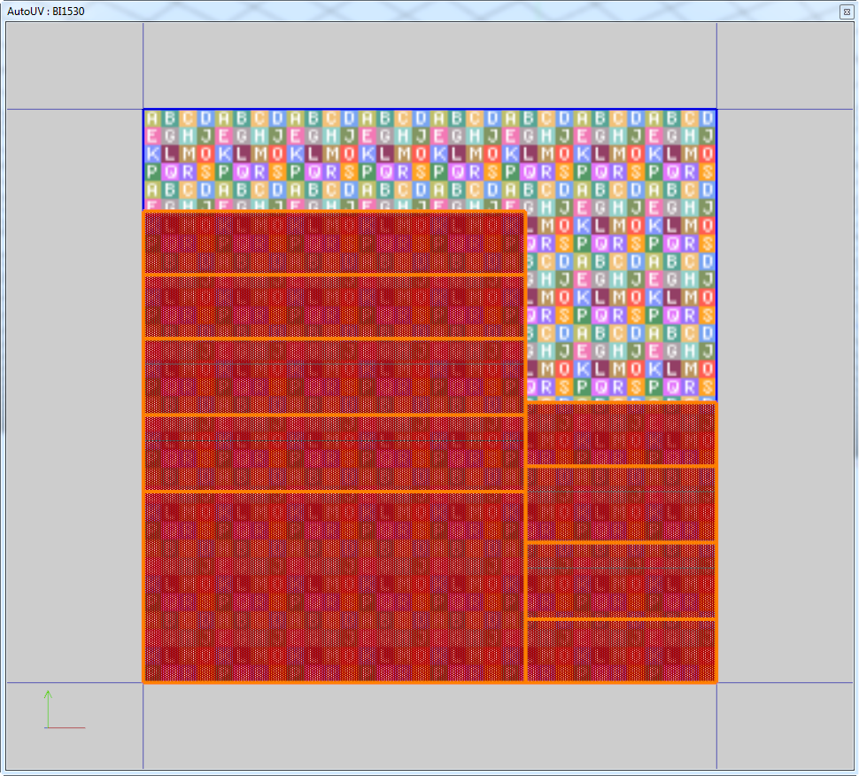
In the Auto UV window you have to arrange the UV Map with stitching in order to have a linear band for the 4 facades and the basements. The isles are then moved to occupy the planned areas. When scaling, the roof and a side facade must be full width and be moved to the top for the roof and to the bottom for the facade. All isles of textures must be aligned with the left border of the map. Attention must be paid to the accuracy of the scale between the frontage of the ground floor and the roof.
Here's what to get
 PH3
PH3
Then you have to create the textures map by R/D -> Create Textures with the standard options.
The textures map is then rendered external and saved in PNG.
In Photoshop or a 2 D drawing software
Creating basic textures
Open the texture map and with vertical guides delimit the 6 zones of patterns and with horizontal guides the stripes attributed to the roof, the basements, the cladding and the ground floor facade. And create closed rectangular paths around each strip so that they can be filled with appropriate textures.
 PH4
PH4
It only remains to create the patterns of roofs and facades to get something harmonious
Finally, we have created quickly 6 different textures which here are examples.
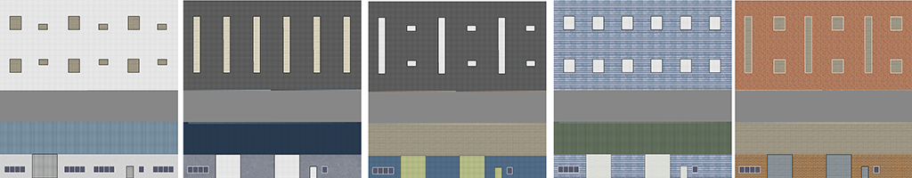 B0
B0
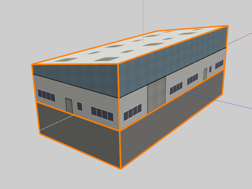
We applied this texture on the base model
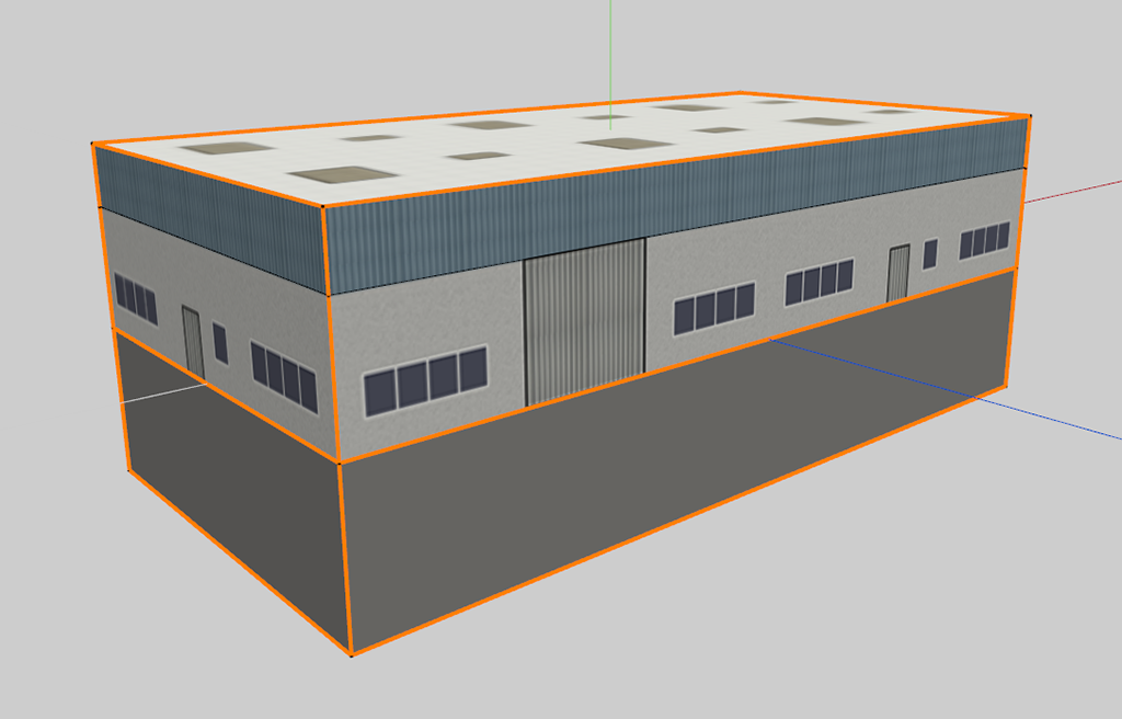 PH6
PH6
 PH 7
PH 7
It is then easy to transform this object into a C3D Condor 2 object.
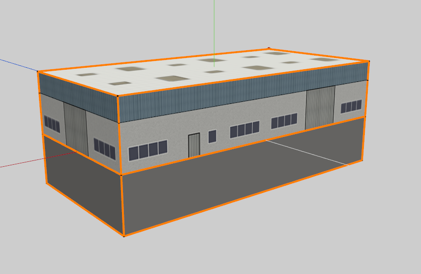
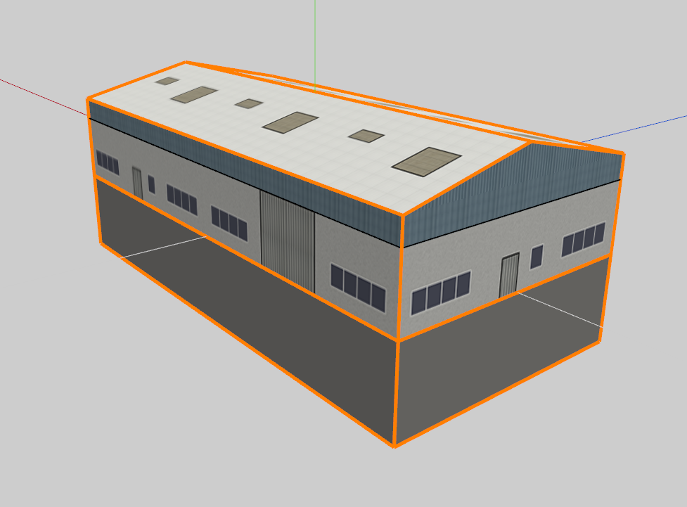
But the most important thing is the versatility of this object:
Without any modification of the texture map, we can increase or decrease the height of the cladding, change the slope of the roof, create a double slope roof in Wings 3D and create as many instances of the same parallelepiped building.
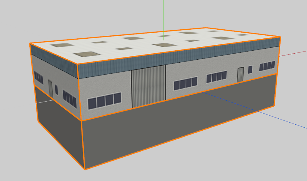 PH8
PH8
 PH9
PH9
 PH10
PH10
But, on the same basis, without changing the texture map, we can increase the width and length of the building by respecting the module of 5 m. However, for each new dimension, width or length, we must adapt the UV Map following the same principles and create a new textures map that will be ultimately identical to the original map.
for example, here is a building of 120 x 60 m
Textures map/UV Map:
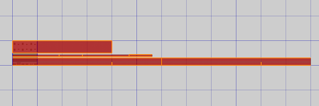 PH11
PH11
The building in Wings 3D:
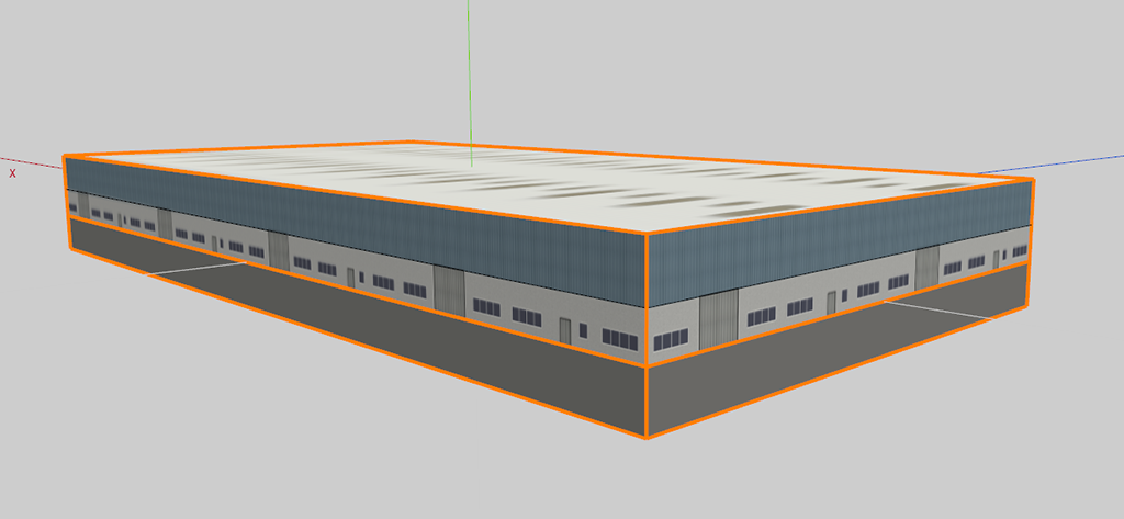 PH12
PH12
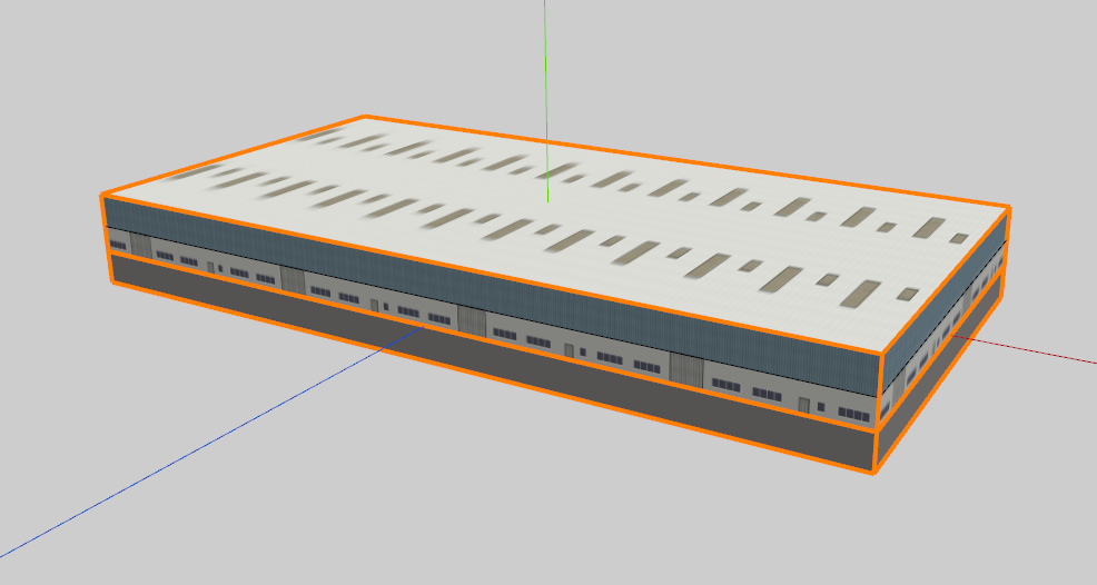 PH13
PH13
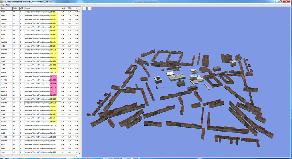
In Object Editor, when the building is larger than the base size, only the base texture will be displayed for the initial dimensions. Do not worry because it will be correctly displayed in Condor 2.
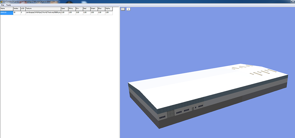 PH14
PH14
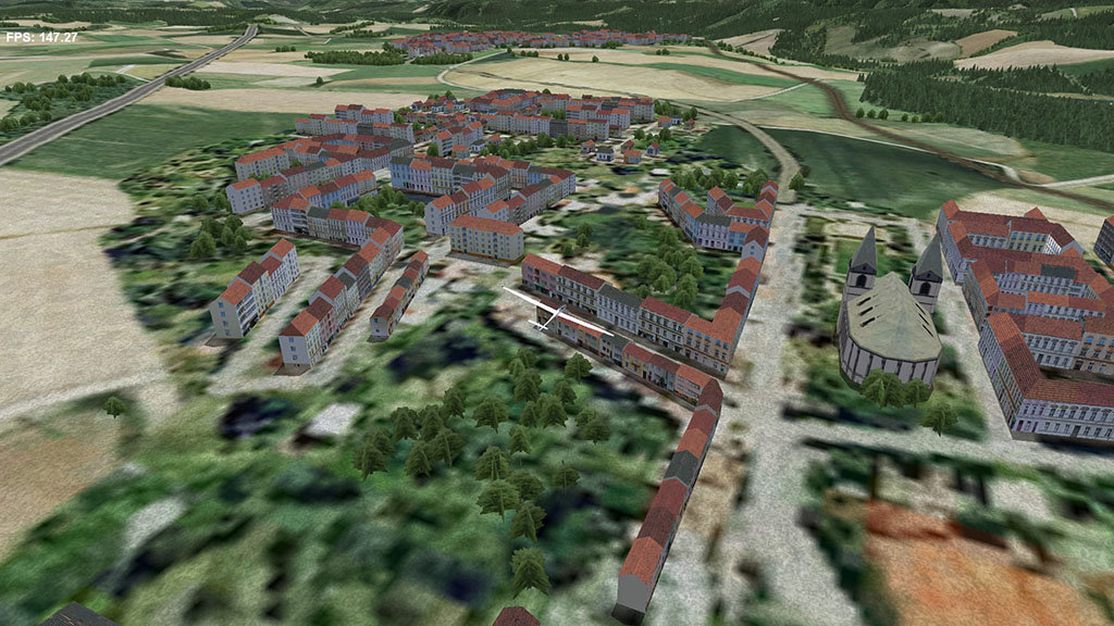
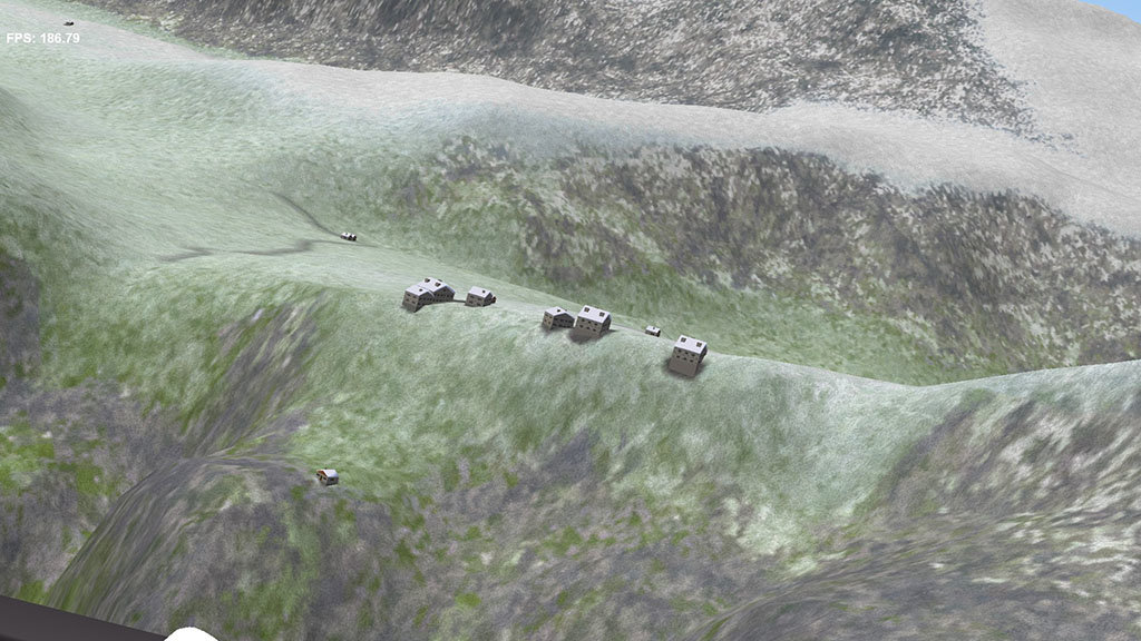
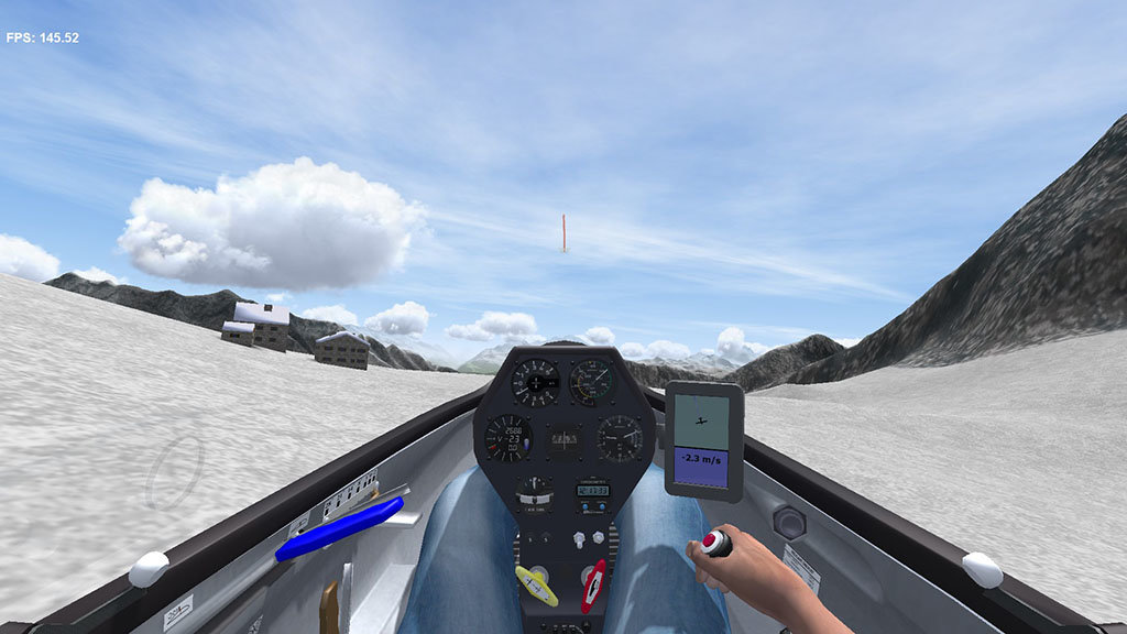
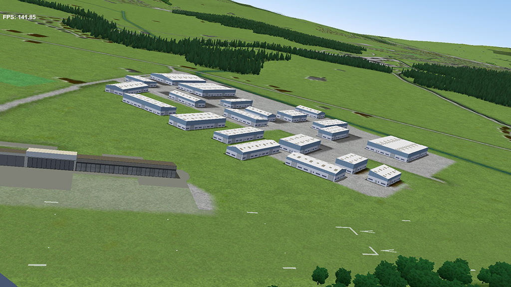
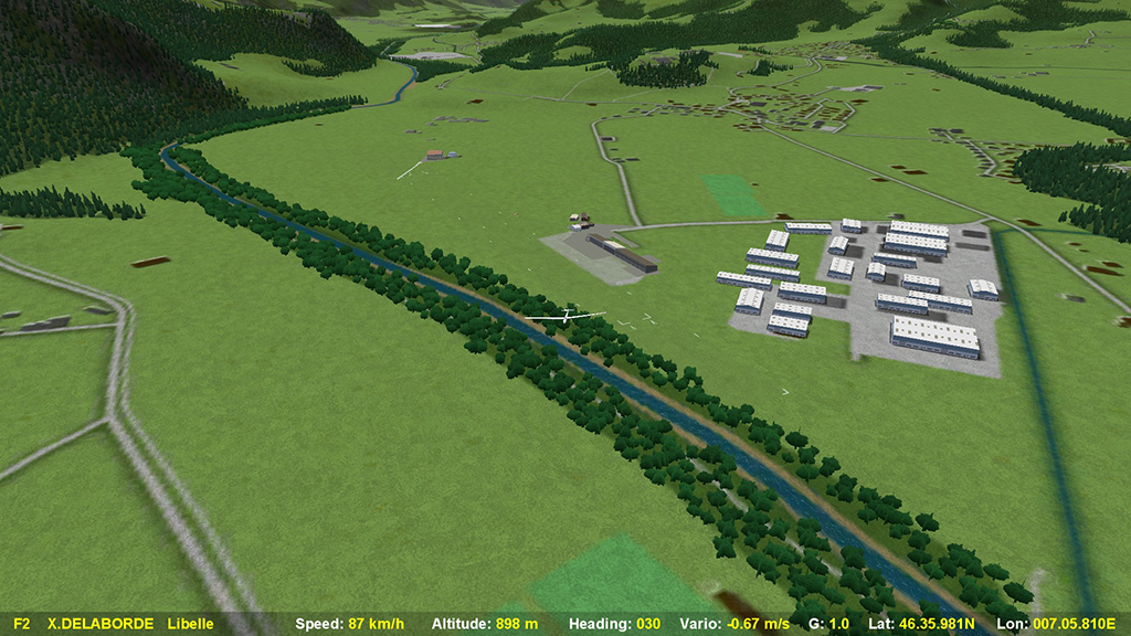
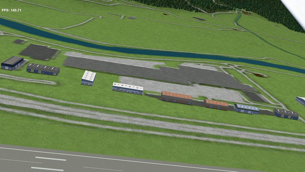
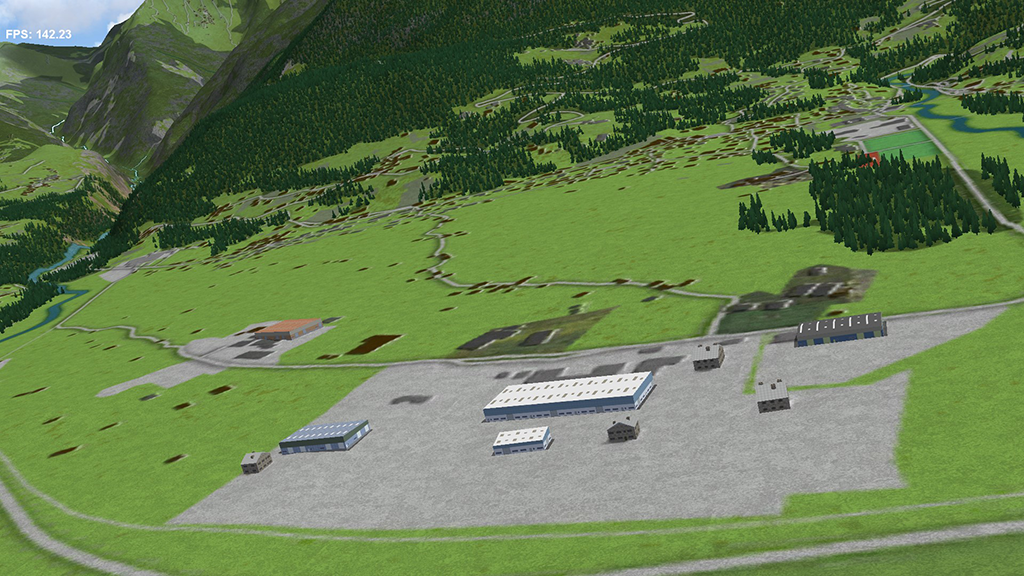
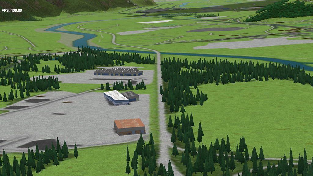
and in Condor 2
Autour de Gruyères
Autour d'Aoste
Autour de Masera Avio Super
Screenshots
Conclusion
This type of object is simple to make and extremely versatile once the limits are clearly explained and fixed. Hundreds of buildings of different sizes can be made and declined on request with as much texture as we can create.
The textures maps in Condor 2 have been decreased to 512x512 pixels.
There is still room in the UV map to create an additional floor at the right scale, by decreasing the space occupied by the stripes for cladding and basements that theoretically can be limited to 10 pixels wide.
Of course it is possible to adapt this type of creation to buildings and houses, cottages etc., so that the Condor 2 sceneries, will always be more realistic.
Generality
We have already shown how to make buildings specifically dedicated to airports in the airport creation guide.
But in the Condor2 scenery, you can see that there are many industrial areas, usually empty of buildings, and that especially around airports.
In order to populate these industrial areas without weakening the FPS, it is necessary to create buildings with simple shapes and to have few textures to be loaded during the simulation.
To realize this type of building, we will use well-known properties of the UV Map because:
- The maps are repeated to infinity in the squares the UV Map.
- The textures are snapped on the vertices of the object unfolded on the map, and if we adopt a vertical or horizontal development there will be little or no deformation, if we take care to make simple roofs.
It is therefore a matter of creating linear textures that are automatically adapted to industrial buildings having a specific module, corresponding to the width or to the height of the texture.
Preliminary choices
The first choice to make is to determine the horizontal or vertical direction that will be used for the texture. For industrial buildings, since there is rarely vertical development, the horizontal direction is chosen. But if we want to create industrial buildings with important vertical development, like silos, we would probably, but not certainly, choose the vertical direction.
To be as versatile as possible, we have decomposed this modular industrial building into four distinct horizontal stripes.
- The roof with these translucent sky domes.
- The facades on the ground floor, including industrial doors, office doors, windows, which must remain at the right scale.
- Facade cladding connecting the ground floor and the roof of a variable height
- Basements, because the ground is not always flat, especially for large industrial buildings and it is illusory to flatten all industrial areas concerned or the floor of each building.
The roofs will be flat, or with one or double slope.
Then we have to make choices for both the building and the texture and after some tests, we have adopted the following provisions:
- A 5 meters module for building facades and roofs
- A basic texture in 1024 × 1024 pixels, which represents a base length of 30 m × 30 m.
A better choice would have been 900 x 900 pixels or 1200 x 1200 pixels because calculations are less complicated to manage.
- A reference building with a flat roof of 30 x 15 m, height 6 m, basement 5 m, with a hole for the bottom.
Each of the four horizontal stripes occupies a determined space in the texture map:
- The roof occupies half of the texture at the top, i.e. 512 pixels and 15 m wide.
- The ground floor facade, 138 pixels to 4 m high
- The cladding, not detached from the facade and above the facade, 172 pixels to 2 m high will be of variable height. The cladding texture will only be made with vertical patterns.
- The basements occupy part of the space between the roof and the facade. Here too, the height of 5 m can be variable to adapt to the terrain. The texture must be with a united or a vertical pattern.
Other choices are obviously possible.
The 5 m module for facades and roofs allows to create 6 vertical zones, thus 6 possibilities to create an original pattern for these 2 entities. This succession of 6 patterns will therefore be repeated along each side of the building and on the roof, provided that the length and width of the building is a multiple of 5 m.
For the roof the succession of 6 patterns (2 are usually enough) will be repeated along the roof in the desired direction, by forcing the width of the roof to the space allocated to the texture.
When the roof has an inclined plane or gables, it is the band reserved for horizontal cladding that will serve as a container and the vertices will be brought back automatically without rebuilding the UV Map.
Making
In wings3D
From a cube we realize the basic module of 15 x 30 m with a height of 6 m that we put on the ground. Then by extrusion we create foundations of 5 m. Then we divide the space of the facades into a ground floor of 4 m and the cladding area of 2 m. The main edges are hardened, and a hole is created on the bottom.
We get this object
PH1We then carry out a standard UV Map
S/E -> L/G on the Object -> O -> R/D -> UV Mapping -> R/D in Auto UV Segmenting -> Segment by -> Projection -> New R/D in UV Segmenting -> Continue -> Normal Projection.
PH2In the Auto UV window you have to arrange the UV Map with stitching in order to have a linear band for the 4 facades and the basements. The isles are then moved to occupy the planned areas. When scaling, the roof and a side facade must be full width and be moved to the top for the roof and to the bottom for the facade. All isles of textures must be aligned with the left border of the map. Attention must be paid to the accuracy of the scale between the frontage of the ground floor and the roof.
Here's what to get
PH3Then you have to create the textures map by R/D -> Create Textures with the standard options.
The textures map is then rendered external and saved in PNG.
In Photoshop or a 2 D drawing software
Creating basic textures
Open the texture map and with vertical guides delimit the 6 zones of patterns and with horizontal guides the stripes attributed to the roof, the basements, the cladding and the ground floor facade. And create closed rectangular paths around each strip so that they can be filled with appropriate textures.
PH4It only remains to create the patterns of roofs and facades to get something harmonious
Finally, we have created quickly 6 different textures which here are examples.
B0We applied this texture on the base model
PH6PH 7It is then easy to transform this object into a C3D Condor 2 object.
But the most important thing is the versatility of this object:
Without any modification of the texture map, we can increase or decrease the height of the cladding, change the slope of the roof, create a double slope roof in Wings 3D and create as many instances of the same parallelepiped building.
PH8PH9PH10But, on the same basis, without changing the texture map, we can increase the width and length of the building by respecting the module of 5 m. However, for each new dimension, width or length, we must adapt the UV Map following the same principles and create a new textures map that will be ultimately identical to the original map.
for example, here is a building of 120 x 60 m
Textures map/UV Map:
PH11The building in Wings 3D:
PH12PH13In Object Editor, when the building is larger than the base size, only the base texture will be displayed for the initial dimensions. Do not worry because it will be correctly displayed in Condor 2.
PH14and in Condor 2
Autour de Gruyères
Autour d'Aoste
Autour de Masera Avio Super
Screenshots
Conclusion
This type of object is simple to make and extremely versatile once the limits are clearly explained and fixed. Hundreds of buildings of different sizes can be made and declined on request with as much texture as we can create.
The textures maps in Condor 2 have been decreased to 512x512 pixels.
There is still room in the UV map to create an additional floor at the right scale, by decreasing the space occupied by the stripes for cladding and basements that theoretically can be limited to 10 pixels wide.
Of course it is possible to adapt this type of creation to buildings and houses, cottages etc., so that the Condor 2 sceneries, will always be more realistic.